PNP vs NPN Sensor Outputs: Differences, Connection Basics & Selection Tips
When selecting industrial sensors—such as photoelectric sensors, proximity switches, or safety devices—one of the most important electrical distinctions to understand is the difference between PNP (sourcing) and NPN (sinking) outputs. Although both output types perform the same essential function—switching a load—they behave very differently in a control system. Choosing the wrong kind can cause wiring errors, false signals, or device incompatibility with your PLC or controller.
This article explains the key differences between PNP and NPN sensor outputs, introduces basic connection concepts, and provides practical selection tips for industrial automation applications.
What Is a PNP (Sourcing) Output?

A PNP output source current to the load. This means that when the sensor is activated, it provides a positive voltage (+V) to the output line. PNP sensors are widely used in Europe, North America, and many modern automation systems because they are well-suited to PLC inputs that expect a positive switching signal.
How PNP Works:
· Brown wire = +V
· Blue wire = 0V
· Black wire = signal output
· Output provides +V to the load when active
· Load is connected between the output and 0V
What Is an NPN (Sinking) Output?

An NPN output sinks current from the load. When the sensor activates, it pulls the output signal down to ground (0V). NPN sensors were historically more common in Asia and in older control systems.
How NPN Works:
· Brown wire = +V
· Blue wire = 0V
· Black wire = signal output
· Output pulls to 0V when active
· Load is connected between +V and the output
Which Type Should You Use—PNP or NPN?
Choosing between PNP and NPN depends on your control system:
✔ Choose PNP (Sourcing) when:
· Your PLC expects positive logic
· You want easier troubleshooting and more common wiring standards
· You follow EU or US industrial automation norms
Most modern control systems prefer PNP.
✔ Choose NPN (Sinking) when:
· Your machine uses older controllers
· You work with systems originally designed for NPN
· Certain Asian-market automation systems require it
Key Differences Between PNP and NPN Sensors
| Feature | PNP (Sourcing) | NPN (Sinking) |
| Active state | Provides +V | Pulls to 0V |
| Wiring style | Load to 0V | Load to +V |
| Common regions | EU, US | Asia |
Compatibility | Preferred by modern PLCs | Used in legacy systems |
How to Avoid Compatibility Issues
To prevent wiring errors, follow these tips:
1. Check PLC Input Type
Determine whether your PLC input cards are PNP-compatible, NPN-compatible, or universal.
2. Match Sensor Output to PLC Input
PNP output → PNP input
NPN output → NPN input
3. Never Swap PNP and NPN
Mixing types can cause:
· Constant ON signals
· No switching response
· Sensor or PLC damage
4. Follow Wire Colour Codes
Most DC sensors follow the IEC standard:
· Brown = +V
· Blue = 0V
· Black = output
Key Insights for Selecting and Wiring PNP vs NPN Sensors
Understanding how PNP and NPN outputs operate is crucial for choosing the right sensor, wiring it correctly, and ensuring seamless integration with industrial control systems. By verifying your PLC's input type, following proper wiring diagrams, and using standard colour-code conventions, you can prevent wiring mistakes, reduce downtime, and maintain stable machine performance.
How to Choose Between PNP and NPN Sensors
Before selecting a sensor, confirm the following:
· PLC input type (sourcing or sinking)
· System standard used in your region or project
· Future expansion requirements
· Maintenance and troubleshooting simplicity
If unsure, consulting the PLC input diagram is more reliable than relying on habit or experience.
Conclusion
PNP and NPN sensor outputs differ fundamentally in output logic and connection behavior, not just wiring style.
Understanding these differences helps engineers avoid compatibility issues, reduce downtime, and improve system reliability.
Recommended Sensors for PNP & NPN Applications

Beam spacing:40mm
Number of optical axes:20
Protection height:760mm
Safety sensors for machines output (OSSD):2 PNP
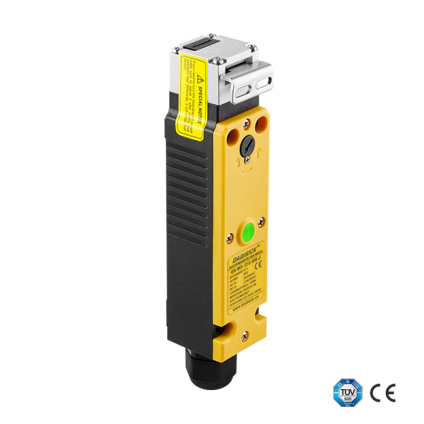
• 2 sets of gold-plated silver alloy contacts
• PA66 flame-retardant housing
• 6 contact combinations
• Locking force 1300 N
• Indicator light + emergency release
• Compatible with 11 types of operating keys
• Compact design saves space

Detection range: 5000 mm, 15000 mm
Material: Nickel-copper alloy
Connection type: 3pin/4pin with 2M cable

Installation type: Non-shielded
Detection range: 8mm, 16mm
Case material: Nickel-plated brass
Connection type: M12 Connector
Output method: NC/NO
Similar Posts You May Be Interested in