How to Wire a Photoelectric Sensor: PNP & NPN Wiring Guide
Correct wiring is essential for stable and reliable photoelectric sensor operation. This article focuses on how to wire and connect photoelectric sensors, explaining wire functions, PNP vs NPN outputs, PLC input matching, and common wiring mistakes. Using the DK-GM12 series through-beam photoelectric sensor as a practical example, this guide helps engineers and technicians avoid installation errors and ensure consistent detection performance.
What is a Photoelectric Sensor

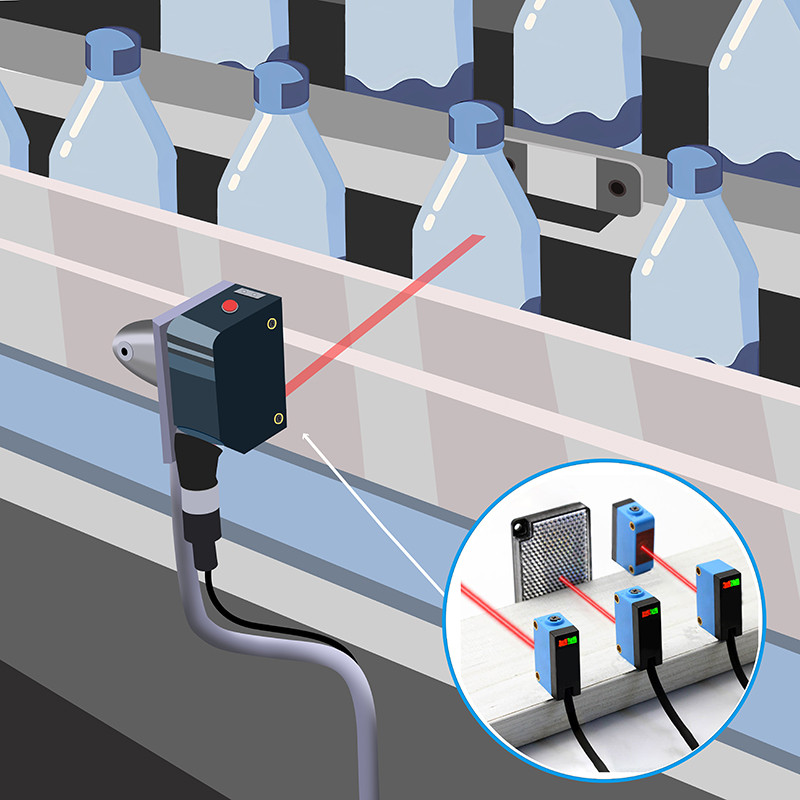
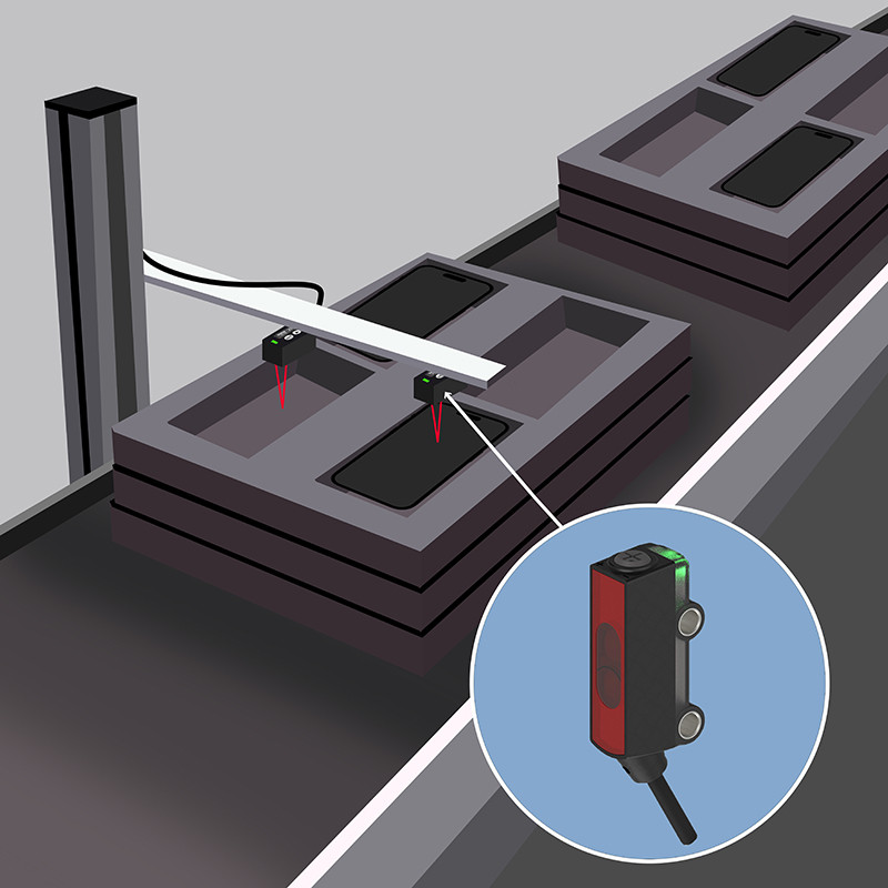
A photoelectric sensor detects objects by emitting a light beam and analyzing changes in the received signal when an object interrupts or reflects that beam. Compared with mechanical switches, photoelectric sensors offer non-contact detection, faster response time, and longer service life, making them ideal for automated production lines.
Why Correct Wiring Matters for Photoelectric Sensors
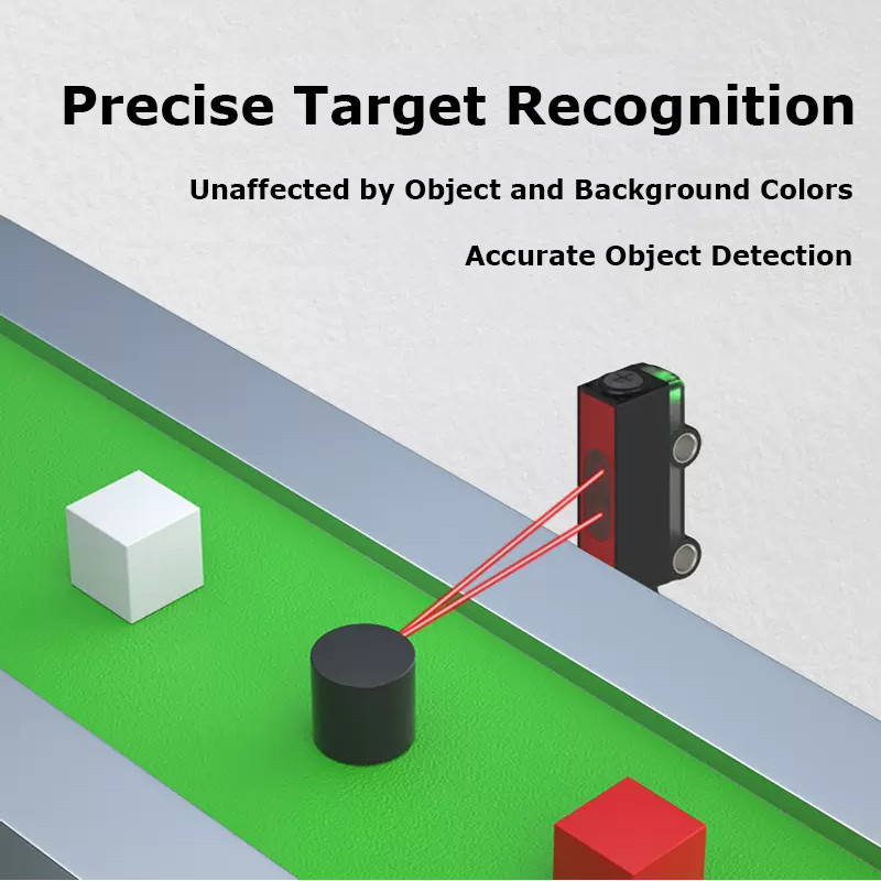
Photoelectric sensors are widely used in industrial automation for object detection, counting, and positioning. However, even a high-quality sensor can perform poorly if it is wired incorrectly.
Common issues caused by improper wiring include:
· No output signal to the PLC
· Unstable or intermittent detection
· False triggering or signal noise
· Permanent sensor damage due to reversed polarity
For this reason, understanding sensor wiring principles is just as important as choosing the right sensor model.
Basic Wiring Structure of a Photoelectric Sensor
Most industrial DC photoelectric sensors, including the DK-GM12 series, use a 3-wire connection.
Standard Wire Colors and Functions
| Wire Color | Function | Description |
| Brown | +V (Power) | Connects to the positive DC supply (usually 24 VDC) |
| Blue | 0V (Ground) | Connects to power supply ground |
| Black | Output | Sends detection signal to PLC or control device |

Always confirm wiring details in the product datasheet before installation.
Understanding PNP and NPN Output Wiring
Before connecting a photoelectric sensor to a PLC, it is critical to identify whether the sensor has a PNP or NPN output, as the signal logic and wiring method are different.
Understanding sourcing and sinking outputs helps prevent mismatched connections between sensors and PLC inputs. For a deeper explanation of output principles and PLC compatibility, refer to PNP vs NPN photoelectric sensor wiring differences.
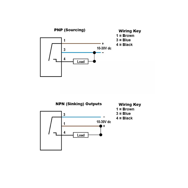
PNP Output Wiring (Sourcing Output)
PNP photoelectric sensors output a positive voltage when an object is detected. This output type is commonly used in European and international automation systems.
PNP wiring logic:
· Brown → +24 VDC
· Blue → 0 V
· Black → PLC input (sourcing signal)
When the sensor detects an object, the black wire outputs +24 V to the PLC input.
Typical use case: Most modern PLCs with sinking inputs.
NPN Output Wiring (Sinking Output)
NPN sensors switch the ground (0 V) side of the circuit when an object is detected. They are still commonly used in some Asian automation systems.
NPN wiring logic:
· Brown → +24 VDC
· Blue → 0 V
· Black → PLC input (sinking output)
When triggered, the sensor pulls the PLC input to ground.
Important note: If an NPN sensor is connected to a PNP PLC input without matching logic, the signal will not be recognized.

Wiring a Through-beam Photoelectric Sensor (DK-GM12 Series Example)
Through-beam photoelectric sensors use two separate units: an emitter and a receiver. This affects wiring and installation.
Power Wiring for Emitter and Receiver
· Emitter: Requires only power (Brown +V, Blue 0V)
· Receiver: Requires power and output wiring (Brown +V, Blue 0V, Black output)
Both units must share the same power supply reference to ensure stable detection.
Alignment and Signal Check
After wiring:
1. Power on the system
2. Align the emitter and receiver until the indicator LED is stable
3. Block the beam to confirm output switching
Incorrect alignment can be mistaken for wiring faults.
Connecting Photoelectric Sensors to PLC Inputs
Before connecting the sensor:
· Confirm PLC input type (PNP or NPN)
· Verify input voltage compatibility
· Check whether the input is sinking or sourcing
Best practice:
Match PNP sensor → sinking PLC input
Match NPN sensor → sourcing PLC input
Common Wiring Mistakes and How to Avoid Them
| Mistake | Result | Prevention |
Reversed polarity | Sensor damage | Double-check power wiring |
PNP/NPN mismatch | No PLC signal | Verify output type |
| Poor grounding | Signal noise | Use proper grounding |
Shared high-voltage cables | Interference | Separate sensor wiring |
How Sensor Type Affects Wiring (Quick Reference)
Sensor type influences wiring complexity, but the basic wiring logic remains the same.
· Through-beam: Two devices need power; the receiver provides output
· Retro-reflective: One device plus reflector; standard 3-wire output
· Diffuse: Simplest wiring; output stability depends on the object surface
Wiring requirements may vary slightly depending on the sensing principle; a general overview is provided in the photoelectric sensor types and selection.
FAQ – Photoelectric Sensor Wiring
Q1: Can I connect a photoelectric sensor directly to a relay?
Yes, as long as the relay input current and voltage match the sensor's output rating.
Q2: What happens if PNP and NPN are mixed?
The PLC will not detect the signal correctly and may remain permanently ON or OFF.
Q3: Why does the sensor output flicker?
Common causes include poor alignment, unstable power supply, or electrical noise.
Conclusion
Correct wiring is the foundation of reliable photoelectric sensor performance. By understanding wire functions, output types, and PLC input matching—and by using practical examples like the DK-GM12 series through-beam photoelectric sensor—engineers can significantly reduce installation errors and system downtime.
Related Safety Devices

Detection range: 5000 mm, 15000 mm
Material: Nickel-copper alloy
Connection type: 3pin/4pin with 2M cable

Detection range: 2000 mm, 3000 mm
Material: Nickel-copper alloy
Connection type: 3pin/4pin with 2M cable

Maximum detection distance: 30-1500mm
Shell material: Plastic, ABS
Connection type: Cable, 4 cores, 2m

Detection range: 2-50mm
Detection range: 2000mm
Casing material: SUS316L
Connection type: Wire lead type (standard wire length 2m)
Similar Posts You May Be Interested in