Since 2006, DADISICK has led industrial automation safety tech globally. We specialize in smart sensor solutions, prioritizing safety, efficiency, and innovation
We provide complete safety perception and protection solutions for industrial automation, smart warehousing, robotics and manufacturing, supporting project customization and rapid implementation.
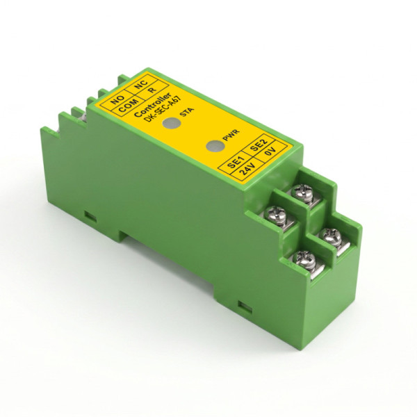
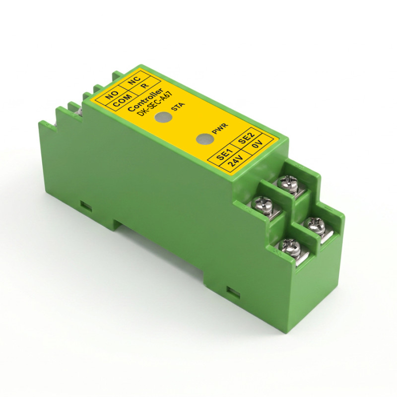
The DK-SEC-A67 is a 35 mm rail-mounted controller that monitors conventional normally open safety edges and safety mats, as well as types fitted with a sensing resistor. It detects and outputs three distinct states — normal, triggered and wire break — through a 1NC+1NO relay safety output.
Wired between the sensing device and the machine control circuit, the unit converts edge or mat contact into a clean, selectable normally open or normally closed signal. Separate STA and PWR indicators show the operating state at a glance, and a buzzer alarms on wire break so a damaged cable is not mistaken for a healthy edge.
DC 12–36V wide-voltage input1NC+1NO DC24V 3A output3 states normal / triggered / wire break
DK-SEC-A67 controller, green ABS rail-mount housing with STA and PWR indicators.
Key Capabilities
Six functions that matter when a pressure-sensitive edge has to fail safely.
01
Three-state detection
Detects and outputs normal, triggered and wire-break states as separate conditions.
02
Selectable NO / NC output
Signal output polarity can be configured as normally open or normally closed to suit the control circuit.
03
Wire-break alarm
A buzzer sounds on wire break, while the STA status indicator lights on both trigger and wire break.
04
Wide-voltage supply
DC 12V to 36V input with DC 24V rated operation, 20 mA maximum current and 0.48 W rated power.
05
Resistor and non-resistor edges
Works with conventional normally open edges and mats, and with types using a series sensing resistor.
06
35 mm rail mounting
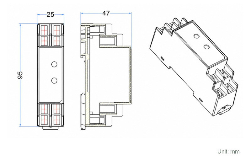
Compact L95 × W25 × H47 mm ABS housing, 70 g ±10%, for dense control cabinets.
Output Logic by Operating State
The COM terminal switches between NC and NO. This is the behaviour printed in the DK-SEC-A67 wiring and diagnostics sheet.
State
COM → NC
COM → NO
STA indicator
Buzzer
Normal
Connected
Disconnected
Off
Off
Triggered
Disconnected
Connected
Lit
Off
Wire break
Disconnected
Connected
Lit
On
Terminal signal assignment: COM is the 0V or 24V common; NC is the trigger and wire-break NC signal; NO is the trigger and wire-break NO signal. The signal output combines wire-break and trigger output.
Terminals & Wiring
Terminal markings
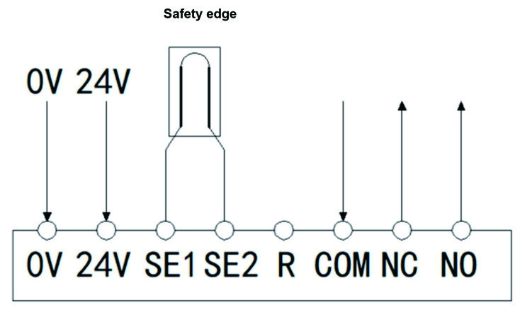
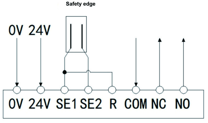
Eight screw terminals are grouped as power, edge inputs and relay output: 0V, 24V, SE1, SE2, R, COM, NC, NO. SE1 and SE2 serve the safety edge input, R the series terminating resistor, and COM / NC / NO the relay contact.
Two wiring configurations
The datasheet provides two separate wiring diagrams: one for a safety edge with a series terminating resistor, and one for a conventional normally open safety edge with no series terminating resistor. Both use the same terminal set and deliver the trigger and wire-break signals at NC and NO. Select the diagram that matches the installed edge before wiring.
On-site checks
If the buzzer alarms, confirm whether a resistor is connected in series with the safety edge. For no output, confirm the edge wiring and the power supply, and confirm that the resistance after triggering is ≤500Ω.
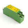
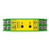
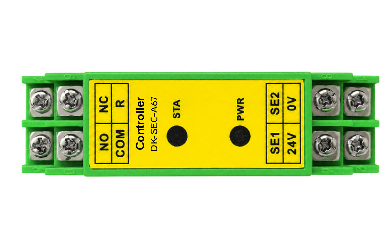
Front panel: NO / NC / COM / R on the output side, SE1 / SE2 / 24V / 0V on the input side.
With a series terminating resistor. Terminals 0V / 24V / SE1 / SE2 / R / COM / NC / NO; NC and NO carry the trigger and wire-break signals.Conventional normally open edge, no series resistor. The same terminal set and signal assignment apply.
Technical Specifications
Rated voltage
DC 24V
Voltage range
DC 12V~36V
Maximum current
20mA
Rated power
0.48W
Safety output
1NC+1NO DC24V 3A
Signal output
Combined wire-break and trigger output
Housing material
ABS
Durability
1,000,000 operations
Operating temperature
-40°C~80°C
Operating humidity
85%RH (no condensation)
Mounting
35mm rail
Dimensions
L95*W25*H47mm
Weight
70g±10%
Terminal markings
NO NC · COM R · SE1 SE2 · 24V 0V · STA PWR
Dimensions
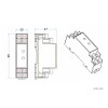
Overall dimensions in millimetres; 35 mm rail clip on the rear face.
L95 × W25 × H47 mm
The narrow 25 mm body fits alongside other rail-mounted safety relays without wasting cabinet width. The dimensional drawing shows front, side and isometric views with the rail clip profile.
Values are taken directly from the DK-SEC-A67 datasheet. For terminal torque, resistor selection and wiring diagrams, refer to the downloadable datasheet or contact our engineers.
Typical Integration
A controller of this type sits between pressure-sensitive protective devices and the machine stop circuit.
Moving machine edges
Monitors edges fitted to powered guards, doors and platforms where closing motion can create a crushing or shearing hazard.
Safety mat zones
Supervises normally open safety mats used to detect personnel entry into a guarded area.
Resistor-monitored devices
Accepts edges and mats with a series terminating resistor, enabling wire-break supervision of the sensing loop.
Control cabinet retrofit
Selectable NO / NC output and 12–36V supply simplify replacement or upgrade of an existing controller.
Frequently Asked Questions
How does the controller distinguish a wire break from a normal trigger?
Both states disconnect COM from NC and connect it to NO, and both light the STA indicator. A wire break additionally triggers the buzzer alarm, so the two conditions can be told apart on site.
Can it work with a safety edge that has no terminating resistor?
Yes. The datasheet gives separate wiring diagrams for a conventional normally open safety edge without a series terminating resistor and for one with a series terminating resistor.
What should be checked when there is no output?
Confirm that the safety edge is properly wired, that the power supply is normal, and that the resistance after the safety edge is triggered is ≤500Ω.
Need the DK-SEC-A67 for your safety circuit?
Tell us the edge or mat type, supply voltage and required output polarity. Our engineers will confirm compatibility and provide the datasheet and wiring diagram.
Let us know how we can help you by completing the form below.
Thank you for your inquiry. We will provide you with professional advice and comprehensive support and services throughout the entire life cycle of your sensor or safety system.
*Email
Name
*Title
*Content
Upload
Only supports .rar/.zip/.jpg/.png/.gif/.doc/.xls/.pdf, maximum 20MB.
Thank you for sharing this information. Our dealer management team will contact you to discuss further cooperation. Please be assured that your inquiry is important to us and we take your privacy seriously.